
Structural Analysis and Design of RCC Buildings Using STAAD.Pro
A practical, step-by-step guide to modelling, loading, analysing and designing a reinforced concrete building in STAAD.Pro to Indian Standards.
Structural Analysis and Design of RCC Buildings Using STAAD.Pro: Introduction
If you are a civil engineering student or a young site or design engineer, sooner or later someone will hand you an architectural plan and ask, “Can you design this in STAAD?” This guide walks you through exactly that: taking a typical RCC residential or commercial building from plan to a designed frame in STAAD.Pro, following Indian Standards.
By the end of this post you will know how to set up the grid and geometry, assign sections and supports, apply dead, live, wind and earthquake loads, create the right load combinations, run the analysis, check whether the results make sense, and design beams and columns to IS 456. The steps work for most versions of STAAD.Pro, from V8i to the CONNECT and 2023+ editions; menu names change slightly, but the logic does not.
Why STAAD.Pro for RCC buildings?
STAAD.Pro, developed by Bentley Systems, is one of the most widely used structural analysis programs in Indian design offices. A few reasons it is popular for RCC buildings:
- Indian codes are built in. Seismic loads to IS 1893, wind loads to IS 875 (Part 3) and concrete design to IS 456 can all be generated and checked inside one model.
- Fast modelling. Structure wizards, grids and translational repeat let you build a multi-storey frame in minutes.
- Editable input file. Every model is also a plain text file, so you can check, copy and reuse commands.
- Industry demand. Many job listings for structural engineers in India ask for STAAD.Pro experience, which makes it a skill worth learning properly.
One honest note before we start: STAAD.Pro analyses and designs the frame (beams and columns). Slabs, footings and detailed reinforcement drawings are usually done separately, either by hand, with spreadsheets or with a tool such as Bentley’s RCDC. Also, always use a licensed copy; students can apply for free educational access through Bentley’s academic programme.
Indian Standards you will need
Keep these codes open while you work. STAAD.Pro applies some of them automatically, but you still choose the inputs.
| Code | What it covers | Where you use it in STAAD |
|---|---|---|
| IS 456:2000 | Plain and reinforced concrete design, load factors (Table 18) | Concrete design of beams and columns, load combinations |
| IS 875 (Part 1):1987 | Unit weights of materials | Self-weight, wall loads, floor finishes |
| IS 875 (Part 2):1987 | Imposed (live) loads | Floor and roof live loads |
| IS 875 (Part 3):2015 | Wind loads | Wind load definition for taller or exposed buildings |
| IS 1893 (Part 1):2016 | Earthquake loads | Seismic definition: zone, soil type, importance and response reduction factors |
| IS 13920:2016 | Ductile detailing of RC structures | Detailing of beams, columns and joints in seismic zones |
| SP 16 and SP 34 | Design aids and detailing handbook | Hand checks and drawings |
The complete workflow in 10 steps
Here is the whole process at a glance. Each step is explained in detail below.
- Study the architectural drawings and fix the column grid.
- Set units and create the geometry (nodes, beams, columns).
- Assign preliminary member sizes and the concrete material.
- Assign supports at the foundation level.
- Define primary load cases: dead, live, wind and seismic.
- Apply the loads: self-weight, floor loads, wall loads.
- Generate load combinations as per IS 456 and IS 1893.
- Run the analysis and read the warnings.
- Check results: reactions, deflections, storey drift and modal participation.
- Design beams and columns to IS 456 and revise sizes until all members pass.
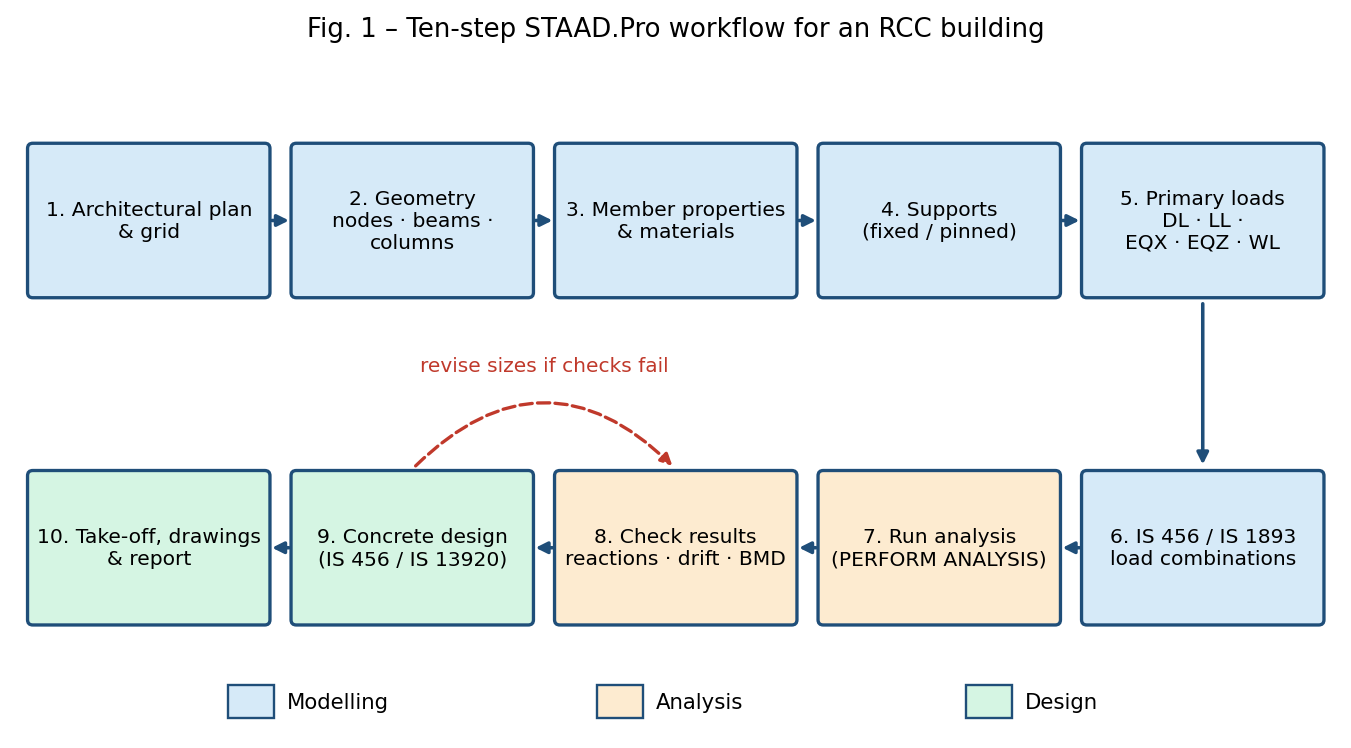
Step-by-step: from plan to designed frame
The example used throughout is a typical G+3 RCC frame building: 3 m storey height, beam spans of 3 to 5 m, 150 mm slabs, 230 mm brick walls, in seismic Zone III on medium soil. Change the numbers to suit your own project.
Step 1: Fix the column grid
Mark column positions on the architectural plan so that columns sit at wall junctions and do not land in doorways or parking lanes. Keep spans between about 3 m and 6 m for economical beams. Write down the X and Z grid distances; you will type these into STAAD.
Step 2: Units and geometry
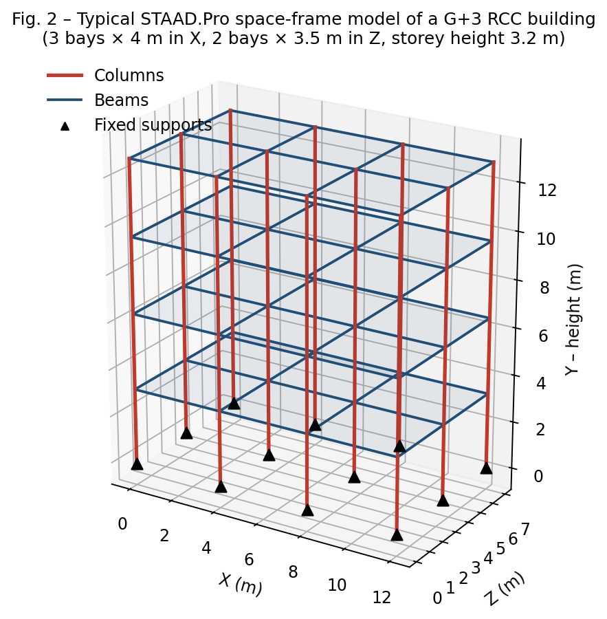
Start a new Space model and set units to metre and kN. Remember that in STAAD the Y axis is vertical by default.
The fastest way to build the frame is: create the grid in plan, draw beams for the first floor, add columns down to the base, then use Translational Repeat in the Y direction to copy the floor for the remaining storeys. Check that no duplicate nodes or beams are left behind (Tools > Check Duplicate).
Step 3: Member sizes and material
For a first run, start with sensible sizes and refine after design. Typical starting sizes for a G+3 residential building:
| Member | Starting size | Notes |
|---|---|---|
| Beams | 230 × 450 mm | Width usually matches the wall thickness |
| Columns | 300 × 450 mm | Orient the longer side along the longer span or the stiffer direction needed |
| Slab | 125 to 150 mm | Not modelled as a member; its load goes on beams through floor load |
Assign them as prismatic sections (Properties > Section Database > Prismatic, YD = depth, ZD = width). Assign concrete as the material, and use M25 or higher for frames in seismic zones. Check column orientation with the beta angle so the stronger axis faces the right way.
Step 4: Supports
Assign fixed supports to all base nodes for an isolated footing design. If you model a plinth beam, place it at plinth level and keep the fixed supports at the footing top.
Step 5: Define primary load cases
Create separate primary load cases so you can combine them later:
| Load case | Type | What goes in it |
|---|---|---|
| EQ +X, EQ +Z (and negative directions if needed) | Seismic | Seismic forces generated from the IS 1893 definition |
| DL | Dead | Self-weight, floor finish, wall loads |
| LL | Live | Floor and roof imposed loads |
| WL +X, WL +Z | Wind | Only where wind may govern (tall, slender or exposed buildings) |
The seismic definition (zone, soil, R, I and the seismic weights) must come before the load cases that use it. Many engineers also number the seismic cases first so that combination numbers stay the same across projects.
Step 6: Apply the loads
Use values from IS 875 (Parts 1 and 2). Typical values for a residential building:
| Load | Typical value | How to apply in STAAD |
|---|---|---|
| Self-weight of frame | Automatic (concrete 25 kN/m³) | Self Weight, factor -1 in Y |
| Slab self-weight (150 mm) | 3.75 kN/m² | Floor Load in global Y |
| Floor finish | 1.0 to 1.5 kN/m² | Floor Load |
| Live load, residential floors | 2.0 kN/m² | Floor Load, in the LL case |
| Live load, accessible roof | 1.5 kN/m² | Floor Load, in the LL case |
| 230 mm brick wall, 3 m storey, 450 mm beam | about 11.5 kN/m (0.23 × 2.55 × 19.6) | Uniform member load on beams |
| Parapet, 1 m high, 115 mm | about 2.3 kN/m | Uniform member load on roof beams |
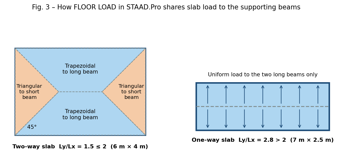
The Floor Load command is the key tool here. You give a Y-range (the level of the floor) and a pressure, and STAAD distributes it to the surrounding beams as one-way or two-way load. This saves you from calculating trapezoidal loads by hand.
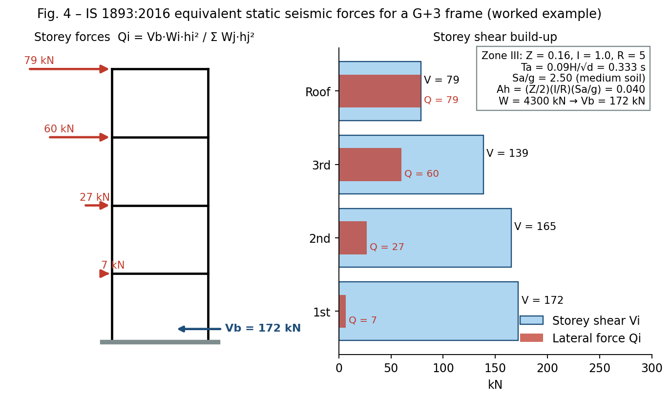
For the seismic definition (IS 1893:2016), you enter:
- Zone factor Z: 0.10 (Zone II), 0.16 (Zone III), 0.24 (Zone IV), 0.36 (Zone V)
- Importance factor I: 1.0 for ordinary buildings, 1.2 for residential or commercial buildings with occupancy above 200 people, 1.5 for important buildings such as hospitals and schools
- Response reduction factor R: 5 for a special moment resisting frame (SMRF) designed and detailed to IS 13920, 3 for an ordinary frame (OMRF)
- Soil type (1 rock, 2 medium, 3 soft), damping (5%), and the period, either calculated by STAAD or entered from the code formula
- Seismic weight: full dead load plus 25% of live load up to 3 kN/m² (50% above that); roof live load is not included
Step 7: Load combinations
The limit state combinations from IS 456 (Table 18) and IS 1893 are:
| Combination | Factors |
|---|---|
| Gravity | 1.5 (DL + LL) |
| Gravity with earthquake | 1.2 (DL + LL ± EQx) and 1.2 (DL + LL ± EQz) |
| Dead with earthquake | 1.5 (DL ± EQx) and 1.5 (DL ± EQz) |
| Uplift check | 0.9 DL ± 1.5 EQx and 0.9 DL ± 1.5 EQz |
| Wind (if applicable) | Same pattern with WL in place of EQ |
For the live load inside the 1.2 combinations, follow clause 6.3 of IS 1893 (Part 1):2016 and your firm’s practice; some offices use the full live load, others the reduced value used for seismic weight. Add serviceability combinations (DL + LL, factor 1.0) for deflection checks and for foundation sizing. STAAD’s Auto Load Combination tool can generate the IS combinations for you, but always open the list and check it.
Step 8: Run the analysis
Add Perform Analysis (with Print Statics Check for a useful summary) and run. Read the warnings in the output file. A clean run with zero errors does not yet mean the model is right, which is why Step 9 matters.
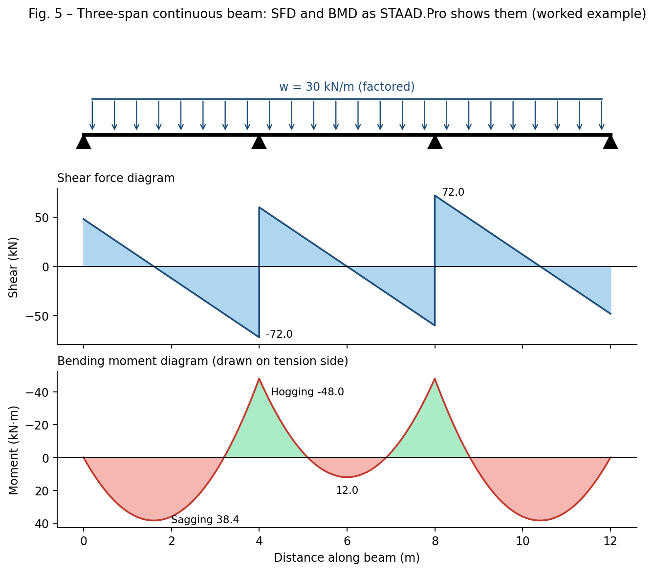
Before design: set the design parameters
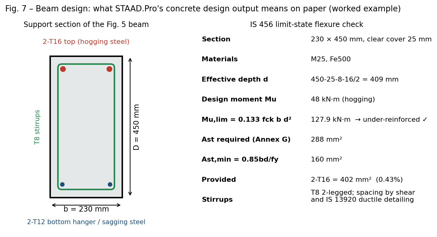
Before design, set the design parameters: concrete grade (FC), steel grade (FYMAIN and FYSEC), clear cover (CLEAR) and member lists for beams and columns. The next section shows a sample input.
Sample STAAD input: loads, combinations and concrete design
You can do everything through the menus, but reading the input file (the STAAD Editor) is the best way to understand and check your model. Below is a trimmed example for the gravity loads, two combinations and the IS 456 design block. Member and node numbers are placeholders; replace them with your own. The seismic definition is best created from the menu (Loading > Seismic Definitions > IS 1893), because the exact keywords differ slightly between STAAD versions.
UNIT METER KN
MEMBER PROPERTY
1 TO 60 PRIS YD 0.45 ZD 0.23
61 TO 100 PRIS YD 0.45 ZD 0.30
CONSTANTS
MATERIAL CONCRETE ALL
SUPPORTS
1 TO 12 FIXED

LOAD 3 LOADTYPE DEAD TITLE DL
SELFWEIGHT Y -1
FLOOR LOAD
YRANGE 2.9 3.1 FLOAD -5.0 GY
YRANGE 5.9 6.1 FLOAD -5.0 GY
MEMBER LOAD
1 TO 40 UNI GY -11.5

LOAD 4 LOADTYPE LIVE TITLE LL
FLOOR LOAD
YRANGE 2.9 3.1 FLOAD -2.0 GY
YRANGE 5.9 6.1 FLOAD -2.0 GY

LOAD COMB 101 1.5(DL+LL)
3 1.5 4 1.5
LOAD COMB 102 1.2(DL+LL+EQX)
1 1.2 3 1.2 4 1.2

PERFORM ANALYSIS PRINT STATICS CHECK

LOAD LIST 101 TO 113
START CONCRETE DESIGN
CODE INDIAN
FC 25000 ALL
FYMAIN 500000 ALL
FYSEC 500000 ALL
CLEAR 0.025 MEMB 1 TO 60
CLEAR 0.040 MEMB 61 TO 100
DESIGN BEAM 1 TO 60
DESIGN COLUMN 61 TO 100
CONCRETE TAKE OFF
END CONCRETE DESIGN
FINISH
A few things to notice:
- In kN-metre units, FC and FY are entered in kN/m², so M25 is 25000 and Fe500 is 500000.
- FLOAD -5.0 in the DL case is the slab self-weight (3.75) plus floor finish (1.25). Wall loads go as UNI member loads.
- Load case 1 here is the seismic case EQ +X, generated from the seismic definition. Add the remaining combinations from the table in Step 7 in the same way.
- LOAD LIST before the design block tells STAAD to design only for the factored combinations, not the unfactored primary cases.
- CONCRETE TAKE OFF gives you the concrete volume and steel weight, which is handy for a rough estimate.
Step 9: Check the results before you trust them
The analysis finishing without errors only means STAAD could solve the equations. These checks tell you whether the model is actually right:
- Total vertical reaction. For the DL case, the sum of support reactions should equal the total dead load you expect. Do a quick hand calculation: floor area × number of floors × load per m², plus wall and frame weights. A difference of more than about 5% means a load is missing or doubled.
- Base shear. Compare the seismic base shear in the output with a hand estimate, VB = Ah × W, where Ah = (Z/2)(I/R)(Sa/g). If STAAD’s value is very different, check the seismic weights and the period.
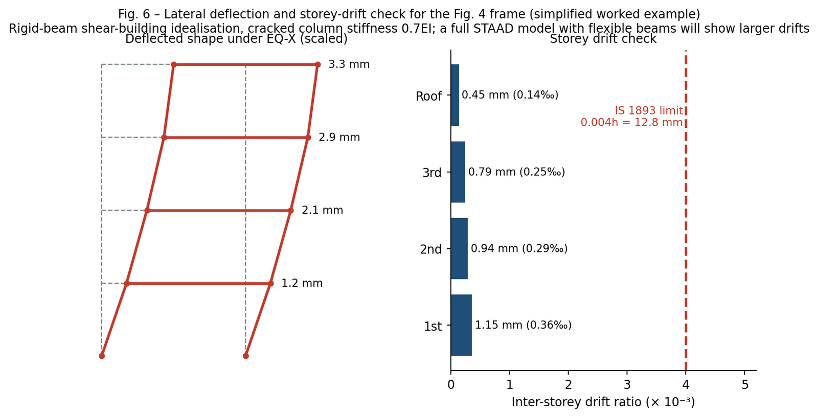
- Deflected shape. Animate the deflection for each load case. The building should sway as a whole under EQ and sag between supports under DL. A single node shooting off means a missing connection or support.
- Storey drift. Under the unfactored earthquake load, the storey drift must not exceed 0.004 times the storey height (IS 1893). For a 3 m storey, that is 12 mm.
- Beam deflection. Keep the span-to-depth ratios of IS 456 (20 for simply supported, 26 for continuous beams, modified for steel) or check deflection under service loads.
- Modal mass participation. If you run response spectrum analysis, include enough modes to capture at least 90% of the mass in each direction.
Common mistakes beginners make
- Applying slab load twice. Using Floor Load for the slab and also adding slab weight as member load doubles the dead load.
- Wrong sign or direction. Loads in the global Y direction must be negative to act downwards (GY -5.0, not +5.0).
- Floor load Y-range that misses the level. If the range 2.9 to 3.1 does not contain the beam level, STAAD silently applies nothing. Check the load diagram after every floor load.
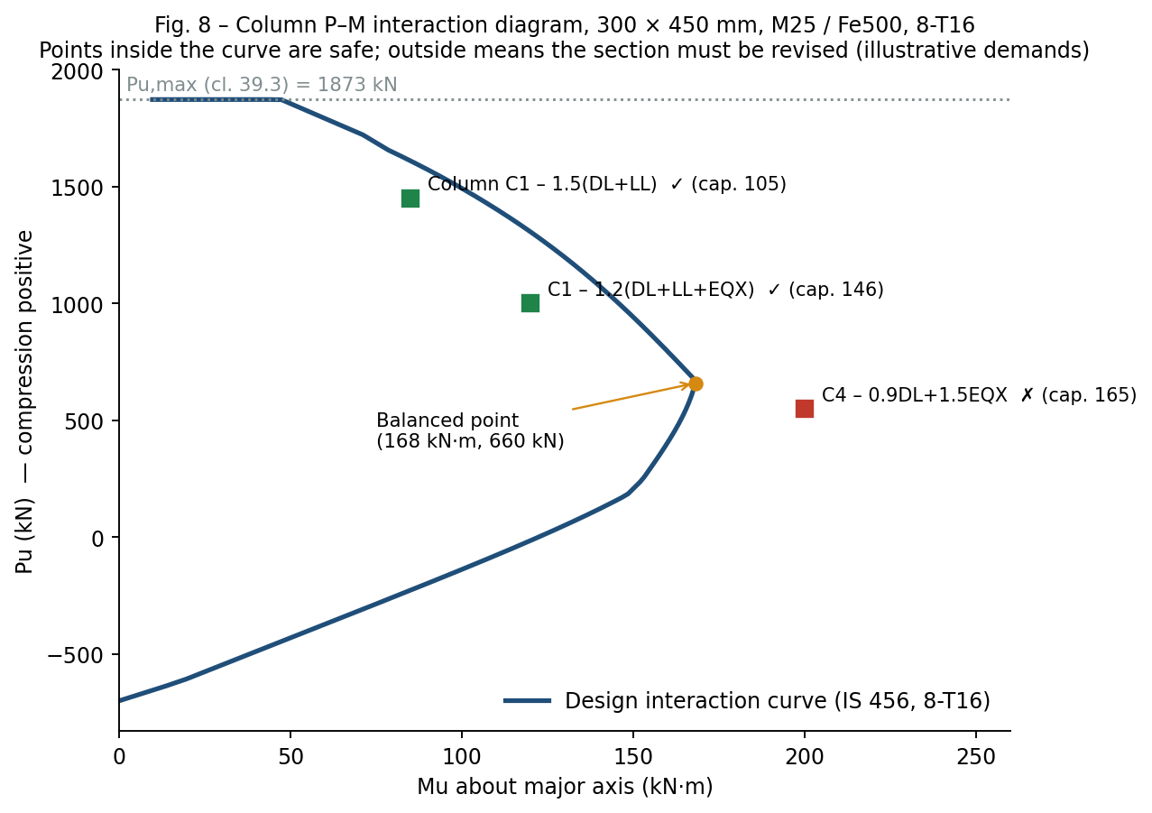
- Columns turned the wrong way. A 300 × 450 column with its strong axis in the wrong direction can fail in design or attract less seismic force than you expect. Check the beta angle.
- Designing for primary load cases. Forgetting LOAD LIST before design makes STAAD design for unfactored loads too.
- Ignoring infill walls in the period. Brick infills stiffen the building. IS 1893:2016 gives Ta = 0.09h/√d for RC frames with masonry infill, which usually gives a shorter period and a higher base shear than a bare frame.
- Trusting design output blindly. STAAD gives required steel areas, not a buildable drawing. Round up to real bar sizes, check bar spacing, and detail joints and stirrups as per IS 13920 in seismic zones.
- Skipping the hand check. One quick hand calculation of total load and base shear catches most modelling errors.
Frequently asked questions
Can STAAD.Pro design slabs and footings? STAAD.Pro mainly analyses and designs the frame. Slabs can be modelled as plates for analysis, but design and detailing of slabs and isolated footings is usually done by hand, with spreadsheets, or with Bentley’s RCDC or STAAD Foundation Advanced.
Should I model the slab as plates or use Floor Load? For ordinary beam-slab buildings, Floor Load is simpler and is standard practice. Model slabs as plates when you need the slab’s stiffness or its own forces, for example in flat slabs or transfer slabs.
Which response reduction factor should I use? Use R = 5 only if the frame is designed and detailed as a special moment resisting frame to IS 13920. Otherwise use R = 3 (ordinary frame), which IS 1893 does not allow in higher seismic zones for most buildings.
What is the difference between seismic coefficient and response spectrum methods? The seismic coefficient (equivalent static) method distributes the base shear over the height using a formula. Response spectrum analysis uses the building’s actual mode shapes. IS 1893:2016 requires dynamic analysis for taller and irregular buildings; check clause 7.7 for the limits.
How do I know my STAAD model is correct? Check that the total vertical reaction matches your hand estimate of the building weight, that the base shear matches VB = Ah × W, and that the deflected shapes look physically sensible.
Is STAAD.Pro free for students? Bentley offers educational access to its software through its academic programme. Use that route rather than unofficial copies, which may give wrong results and carry legal and security risks.
Conclusion
Designing an RCC building in STAAD.Pro comes down to a clear sequence: a sensible grid, correct sizes and supports, honest loads from IS 875 and IS 1893, the right IS 456 combinations, careful result checks, and finally design and detailing. The software does the heavy calculation, but the engineering judgement in each step is yours.
If this guide helped you, practise it on a small G+1 or G+2 plan first, then move to taller buildings and response spectrum analysis. In the next posts in this series we cover response spectrum analysis in STAAD.Pro, isolated footing design to IS 456, and detailing of beams and columns to IS 13920.
Have a question about your own model? Leave it in the comments below, and subscribe so you don’t miss the next tutorial.
Disclaimer: This article is for learning purposes. The figures and numbers are worked examples, not results from a real project. Any real building must be analysed, designed and checked by a qualified structural engineer as per the current Indian Standards.